- 您现在的位置:买卖IC网 > Sheet目录3840 > PIC18F6410-I/PT (Microchip Technology)IC PIC MCU FLASH 8KX16 64TQFP
PIC18F66K80 FAMILY
DS39977F-page 204
2010-2012 Microchip Technology Inc.
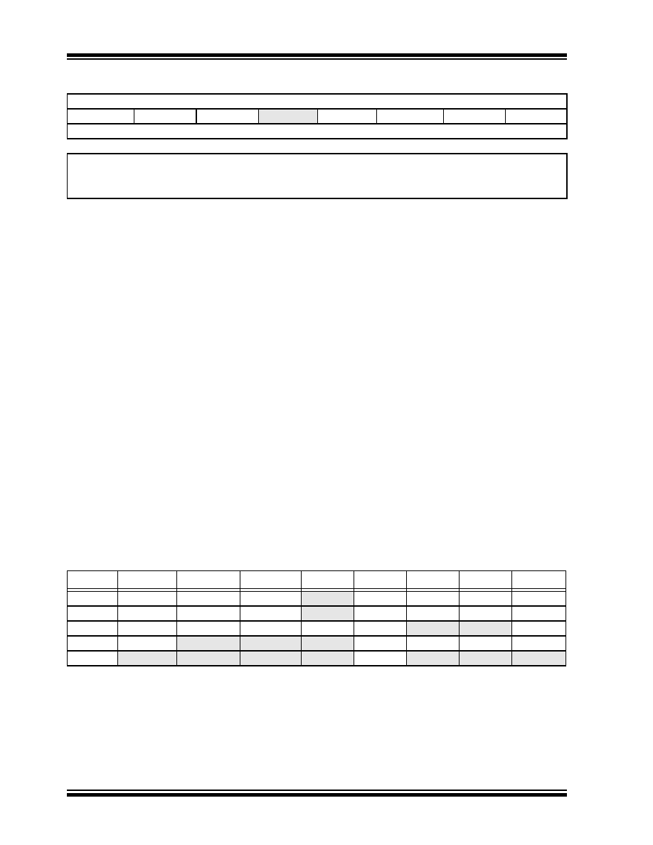
TABLE 12-1:
SUMMARY OF REGISTERS ASSOCIATED WITH DATA SIGNAL MODULATOR MODE
REGISTER 12-4:
MDCARL: MODULATION LOW CARRIER CONTROL REGISTER
R/W-0
R/W-x
U-0
R/W-x
MDCLODIS
MDCLPOL
MDCLSYNC
—
MDCL3(1)
MDCL2(1)
MDCL1(1)
MDCL0(1)
bit 7
bit 0
Legend:
R = Readable bit
W = Writable bit
U = Unimplemented bit, read as ‘0’
-n = Value at POR
‘1’ = Bit is set
‘0’ = Bit is cleared
x = Bit is unknown
bit 7
MDCLODIS:
Modulator Low Carrier Output Disable bit
1
= Output signal driving the peripheral output pin (selected by MDCL<3:0> of the MDCARL register)
is disabled
0
= Output signal driving the peripheral output pin (selected by MDCL<3:0> of the MDCARL register)
is enabled
bit 6
MDCLPOL:
Modulator Low Carrier Polarity Select bit
1
= Selected low carrier signal is inverted
0
= Selected low carrier signal is not inverted
bit 5
MDCLSYNC:
Modulator Low Carrier Synchronization Enable bit
1
= Modulator waits for a falling edge on the low time carrier signal before allowing a switch to the high
time carrier
0
= Modulator output is not synchronized to the low time carrier signal(1)
bit 4
Unimplemented:
Read as ‘0’
bit 3-0
MDCL<3:0>
Modulator Data High Carrier Selection bits(1)
1111
-1001 = Reserved
1000
= CCP5 output (PWM Output mode only)
0111
= CCP4 output (PWM Output mode only)
0110
= CCP3 output (PWM Output mode only)
0101
= CCP2 output (PWM Output mode only)
0100
= ECCP1 output (PWM Output mode only)
0011
= Reference clock module signal
0010
= MDCIN2 port pin
0001
= MDCIN1 port pin
0000
= VSS
Note 1:
Narrowed carrier pulse widths or spurs may occur in the signal stream if the carrier is not synchronized.
Name
Bit 7
Bit 6
Bit 5
Bit 4
Bit 3
Bit 2
Bit 1
Bit 0
MDCARH MDCHODIS
MDCHPOL MDCHSYNC
—
MDCH3
MDCH2
MDCH1
MDCH0
MDCARL
MDCLODIS
MDCLPOL
MDCLSYNC
—
MDCL3
MDCL2
MDCL1
MDCL0
MDCON
MDEN
MDOE
MDSLR
MDOPOL
MDO
—
—MDBIT
MDSRC
MDSODIS
—
MDSRC3
MDSRC2
MDSRC1
MDSRC0
PMD2
—
—MODMD
ECANMD
CMP2MD
CMP1MD
Legend:
— = unimplemented, read as ‘0’. Shaded cells are not used in the Data Signal Modulator mode.
发布紧急采购,3分钟左右您将得到回复。
相关PDF资料
200346-2
CONN HOUSING RECEPT 20POS BLACK
PIC16F84A-20/P
IC MCU FLASH 1KX14 EE 18DIP
200838-2
CONN HOUSING RECEPT 34POS BLACK
PIC18LF2420-I/SO
IC MCU FLASH 8KX16 28SOIC
5172625-3
CONN RCPT HSNG 24POS BLUE PNL MT
202758-1
CONN HOUSING PLUG 6POS BLACK
TS80C31X2-VIC
IC MCU 8BIT 40/30MHZ 44-PQFP
TS80C31X2-MCC
IC MCU 8BIT 40/20MHZ 44-PQFP
相关代理商/技术参数
PIC18F6410-I/PT
制造商:Microchip Technology Inc 功能描述:IC 8BIT FLASH MCU 18F6410 TQFP64
PIC18F6410T-I/PT
功能描述:8位微控制器 -MCU 16kBF 768RM 68I/O RoHS:否 制造商:Silicon Labs 核心:8051 处理器系列:C8051F39x 数据总线宽度:8 bit 最大时钟频率:50 MHz 程序存储器大小:16 KB 数据 RAM 大小:1 KB 片上 ADC:Yes 工作电源电压:1.8 V to 3.6 V 工作温度范围:- 40 C to + 105 C 封装 / 箱体:QFN-20 安装风格:SMD/SMT
PIC18F6490-E/PT
功能描述:8位微控制器 -MCU 16kBF 768RM 68I/O RoHS:否 制造商:Silicon Labs 核心:8051 处理器系列:C8051F39x 数据总线宽度:8 bit 最大时钟频率:50 MHz 程序存储器大小:16 KB 数据 RAM 大小:1 KB 片上 ADC:Yes 工作电源电压:1.8 V to 3.6 V 工作温度范围:- 40 C to + 105 C 封装 / 箱体:QFN-20 安装风格:SMD/SMT
PIC18F6490-I/PT
功能描述:8位微控制器 -MCU 16kBF 768RM 68I/O RoHS:否 制造商:Silicon Labs 核心:8051 处理器系列:C8051F39x 数据总线宽度:8 bit 最大时钟频率:50 MHz 程序存储器大小:16 KB 数据 RAM 大小:1 KB 片上 ADC:Yes 工作电源电压:1.8 V to 3.6 V 工作温度范围:- 40 C to + 105 C 封装 / 箱体:QFN-20 安装风格:SMD/SMT
PIC18F6490-I/PT
制造商:Microchip Technology Inc 功能描述:IC 8BIT FLASH MCU 18F6490 TQFP64
PIC18F6490-I/PT
制造商:Microchip Technology Inc 功能描述:8 BIT MICROCONTROLLER CLOCK SPEED:40MHZ
PIC18F6490T-I/PT
功能描述:8位微控制器 -MCU 16kBF 768RM 68I/O RoHS:否 制造商:Silicon Labs 核心:8051 处理器系列:C8051F39x 数据总线宽度:8 bit 最大时钟频率:50 MHz 程序存储器大小:16 KB 数据 RAM 大小:1 KB 片上 ADC:Yes 工作电源电压:1.8 V to 3.6 V 工作温度范围:- 40 C to + 105 C 封装 / 箱体:QFN-20 安装风格:SMD/SMT
PIC18F6493-I/PT
功能描述:8位微控制器 -MCU 128 Segmnt LCD DRVR 12B ADC 16KB 768BRAM RoHS:否 制造商:Silicon Labs 核心:8051 处理器系列:C8051F39x 数据总线宽度:8 bit 最大时钟频率:50 MHz 程序存储器大小:16 KB 数据 RAM 大小:1 KB 片上 ADC:Yes 工作电源电压:1.8 V to 3.6 V 工作温度范围:- 40 C to + 105 C 封装 / 箱体:QFN-20 安装风格:SMD/SMT